19
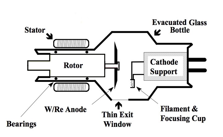
X-rays are electromagnetic radiation produced in an evacuated glass tube (bottle in the image below). A spinning tungsten anode is the target for high velocity electrons that have been accelerated across the vacuum in the tube by a large voltage differential between the cathode and the anode. When the electrons strike the anode, x-rays are liberated along with heat. X-rays are only produced when there is a voltage differential applied across the cathode and anode, therefore, the x-ray tube is dormant until activated by the Medical Radiation Technologist (MRT). This physical, on/off, arrangement is used for all modalities that employ x-rays for imaging (X-ray, CT, Fluoroscopy, Angiography). (Figure 3.3)
The quantity and energy of the x-rays produced is controlled by the parameters set on the machine by the MRT. Every effort is made to optimize the exposure factors to minimize radiation dose, but there are times when the patient receives too few, or too many, x-rays resulting in a poor quality image. Often, this can be managed by adjusting the contrast and brightness of the display monitor during viewing, but rarely some images must be repeated in order for them to be of diagnostic quality.
The x-rays that result from the electron bombardment of the anode are constrained within a heavy lead housing that contains circulating oil to cool the tube. The dispersal of the x-ray beam is limited to a small port in the lead housing of the x-ray tube and by mechanical metal filters that collimate the x-ray beam and prevent the uncontrolled, dissemination of x-rays. Therefore, the emitted x-rays expose only the desired region of the patient’s anatomy in a controlled manner. The limitation of the x-rays by the lead housing and the collimation filters is how small part x-rays, i.e. wrist, scaphoid bone, can be done, as well as, large field x-rays such as a full field chest x-ray. (Figure 3.4)
The x-rays pass through the patient to reach an x-ray detector on the other side of the patient. Historically, x-rays were photo-emulsion embedded in plastic sheets that required development in a processor of developer and fixer solutions after exposure to diagnostic x-rays. The dried radiographic images were stored as hard-copies for viewing. The image detectors used today rely on complex electronic systems that converts x-rays into electrical signals that then results in pixels of different intensity on the monitor of a digital display system.
The radiographic (x-ray) image has been described by Dr. Lucy Squire as a, “summation shadowgram”, highlighting the fact that the final image is a summation of all the interactions between the anatomy of the patient and the original x-ray beam prior to the beam reaching the x-ray detector. The x-ray beam is altered by absorption and scattering before it finally reaches the x-ray detector. The resulting image ranges between bright white to dark black with hundreds of shades of grey in between. This phenomenon is analogous to black and white photographic emulsion as those areas with more light exposure are blacker on the photograph. The digital image creation process is depicted in Figure 3.5.

Figure 3.6 (A-D) depict two common types of x-ray imaging devices, one a static wall mounted unit in an x-ray room and the second, portable units that can be moved to the patient.
Fixed, Wall, x-ray Detector

Portable x-ray Machine

Portable x-ray Machine, tube extended

Portable C-arm x-ray machine

Image Appearance
There are five ‘basic’ opacities in x-ray imaging, with differential x-ray absorption capabilities – air, fat, soft tissue, bone, and metal. Air has a simple molecular structure, allowing a large proportion of the incident x-ray beam to pass through and reach the image detector, resulting in a dark region on x-ray images. Metal, on the other hand, is a dense structure with heavier atomic weights among the atoms of the metal. Conversely, metal absorbs a large proportion of the incident x-ray beam. Metal is depicted on images as bright white. Metal absorbs more of the incident x-rays than bone (cortical and medullary bone) and therefore, is whiter than bone on the resulting image.
Figure 3.7 demonstrates the appearance of an image with the five boxes representing the relative image opacity. From left to right the opacities are air, fat, soft tissue, bone, and metal.
X-ray gray-scale

Opaque (opacity) – an area of the patient that absorbed, or scattered, a large amount of the incident x-ray beam prior to it reaching the detector, i.e. the tissues in question block the x-rays from reaching the detector (whiter on the x-ray image). For example, one would describe metal as opaque on x-ray imaging.
Lucent (lucency) – an area of the image where a larger amount of the x-ray beam passed through unimpeded to reach the detector (blacker on the x-ray image). For example, one would describe air as lucent on x-ray imaging.
A clinical example of the different absorption spectra seen on x-rays is provided in Figure 3.8. This is an image of a patient with a knife embedded in his left shoulder.

- The x-ray (summation shadowgram) of the shoulder reveals a very opaque (white) object consistent with the metallic blade of a knife.
- The handle of the knife is made of plastic and was very lucent compared to the metal. The metal knife blade is embedded in the bone of the proximal humerus.
- Note the differential opacity of the cortical bone vs. the medullary bone, The cortical bone is more compact and opaque as it has more calcium than the medullary bone which has marrow containing fat (more lucent).
- The air external to the patient is very lucent (black) as a large amount of the original x-rays reached the detector.
- The lung (seen on the left side of the image) has a low density but is more dense than the surrounding air due to the summation of all the other anatomy from dorsal to ventral in the chest, however, it is still quite lucent compared to other regions of the image.
- One can see tissue planes between the muscles of the arm, in particular the bicep and deltoid muscles, as there is fat in between these muscles and fat is more lucent than muscle.
- Note the contrast between the density of fat between the muscles and gas trapped in the dressing applied to the entry site of the knife. The air is darker (more lucent).
Thickness of the imaged anatomy also effects x-ray absorption. This is depicted in Figure 3.9.

This is depicted on a quality control image taken for x-ray tube calibration. Figure 3.10 shows an x-ray of a Lucite plastic plate with variable depth holes drilled into it causing the appearance of the circles. The circles become more lucent as the thickness of the Lucite diminishes. The vertical stripes are progressively thicker layers of aluminum that has been applied to the Lucite.

X-ray Image Appearance:
- 5 Basic Opacities (Air, Fat, Soft Tissue, Bone, and Metal)
- Opaque (opacity) – an area that absorbs or scatters a large amount of x-ray beams before they reach the detector. Appear whiter on an x-ray
- Lucent (lucency) – an area where x-ray beams pass through without interference to reach the detector. Appear blacker on an x-ray
- Thickness of tissue also effects x-ray absorption
Patient Positioning for x-ray images
Most x-ray equipment has a relatively fixed positions of the x-ray tube and the x-ray detector. In order to acquire images in different anatomic projections the patient must be moved and positioned. This may require the image detector to be on a wall or table mounted apparatus or the detector may be in a hand-held cassette. The patient may need to be quite mobile for some images i.e. they need to lie on their side or stand upright.
A basic tenet of plain x-rays is to obtain at least two views of the anatomy in question, usually taken 90 degrees apart from each other (orthogonal). One of the images is usually obtained in anatomic position and the second image is 90 degrees to the original anatomic position. Therefore, the minimum two views are usually a anterior-posterior (AP) and a lateral. If the x-rays enter the patient from the posterior anatomic side the image will be called a posterior-anterior (PA) view.
Some anatomy is better assessed by obtaining additional views i.e. odontoid view for the high cervical spine, axillary view of the shoulder, skyline view of the patella. These special views must be requested at the time of completing the original request form in order for them to be included with the standard image set. Some special views take advantage of the fact that air rises in any space and fluid falls with gravity, i.e. gas in the peritoneal space and mobile pleural fluid on the decubitus chest x-ray. Also, taking an image in expiration can facilitate the detection of a pneumothorax due to the elastic recoil of the lung on expiration and a reduction in gas within the lung at full expiration.
It may be difficult to obtain quality images, if the patient is unconscious, traumatized, in pain, or uncooperative. This must be kept in mind when requesting x-ray examinations.
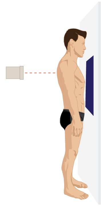
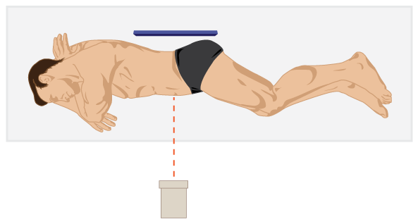
Examples of PA and Lateral chest x-ray positioning are shown in Figure 3.11A and 3.11B while a left side up Decubitus, Abdomen x-ray is seen in Figure 3.11C.
Posterior-Anterior Chest x-ray
Lateral Chest x-ray

Decubitus x-ray
Radiation Exposure: X-rays
X-rays are ionizing radiation. Thus, x-rays can cause tissue ionization and this can result in genetic alterations. The majority of the genetic alterations that occur do not lead to cellular damage and lead to no adverse genetic events or genetic mutation. However, it is practical, and appropriate, to minimize radiation exposure whenever possible. The, As Low As Reasonably Achievable approach (the ALARA principle) is an excellent strategy to employ in order to reduce the exposure of patients to x-rays. In addition, Appropriateness Guidelines (CAR, ACR, ESR), and strategies such as, “Choosing Wisely” and , “Imaging Gently” are also geared towards minimizing x-ray utilization if not clinically safe, appropriate. or helpful in managing the patient’s medical condition.
Attributions
Fig 3.3 X-ray Tube by Kieranmaher is in the Public Domain.
Fig 3.4 X-ray Tube. Lead Housing with Portal for x-ray Emission, bench top image by Rschiedon is available under a CC-BY-SA 3.0 Unported License.
Fig 3.5 X-ray Image Creation and Display by Dr. Brent Burbridge MD, FRCPC, University Medical Imaging Consultants, College of Medicine, University of Saskatchewan is used under a CC-BY-NC-SA 4.0 license.
Fig 3.6A A standard, fixed location, wall x-ray detector used for upright chest and abdomen x-rays by Dr. Brent Burbridge MD, FRCPC, University Medical Imaging Consultants, College of Medicine, University of Saskatchewan is used under a CC-BY-NC-SA 4.0 license.
Fig 3.6B A Portable x-ray Machine by Dr. Brent Burbridge MD, FRCPC, University Medical Imaging Consultants, College of Medicine, University of Saskatchewan is used under a CC-BY-NC-SA 4.0 license.
Fig 3.6C The Portable x-ray machine with the x-ray tube extended for use by Dr. Brent Burbridge MD, FRCPC, University Medical Imaging Consultants, College of Medicine, University of Saskatchewan is used under a CC-BY-NC-SA 4.0 license.
Fig 3.6D A Portable, Mini, C-Arm x-ray Unit by Dr. Brent Burbridge MD, FRCPC, University Medical Imaging Consultants, College of Medicine, University of Saskatchewan is used under a CC-BY-NC-SA 4.0 license.
Fig 3.7 Appearance of different entities on x-rays by Dr. Brent Burbridge MD, FRCPC, University Medical Imaging Consultants, College of Medicine, University of Saskatchewan is used under a CC-BY-NC-SA 4.0 license.
Fig 3.8 Left Shoulder x-ray by Dr. Brent Burbridge MD, FRCPC, University Medical Imaging Consultants, College of Medicine, University of Saskatchewan is used under a CC-BY-NC-SA 4.0 license. Accessible from https://mistr.usask.ca/odin/?caseID=20160214201450302
Fig 3.9 Effect of tissue thickness on x-ray appearance by Dr. Brent Burbridge MD, FRCPC, University Medical Imaging Consultants, College of Medicine, University of Saskatchewan is used under a CC-BY-NC-SA 4.0 license.
Fig 3.10 Common x-ray Test Object, Lucite Plastic Board by Dr. Brent Burbridge MD, FRCPC, University Medical Imaging Consultants, College of Medicine, University of Saskatchewan is used under a CC-BY-NC-SA 4.0 license.
Fig 3.11A Posterior-anterior, upright, chest x-ray positioning, by the Distance Education Unit, University of Saskatchewan, is published using a CC-BY-NC-SA 4.0 International License.
Fig 3.11B Lateral, upright, chest x-ray positioning, by the Distance Education Unit, University of Saskatchewan, is published using a CC-BY-NC-SA 4.0 International License.
Fig 3.11C Decubitus x-ray positioning, by the Distance Education Unit, University of Saskatchewan, is published using a CC-BY-NC-SA 4.0 International License.
